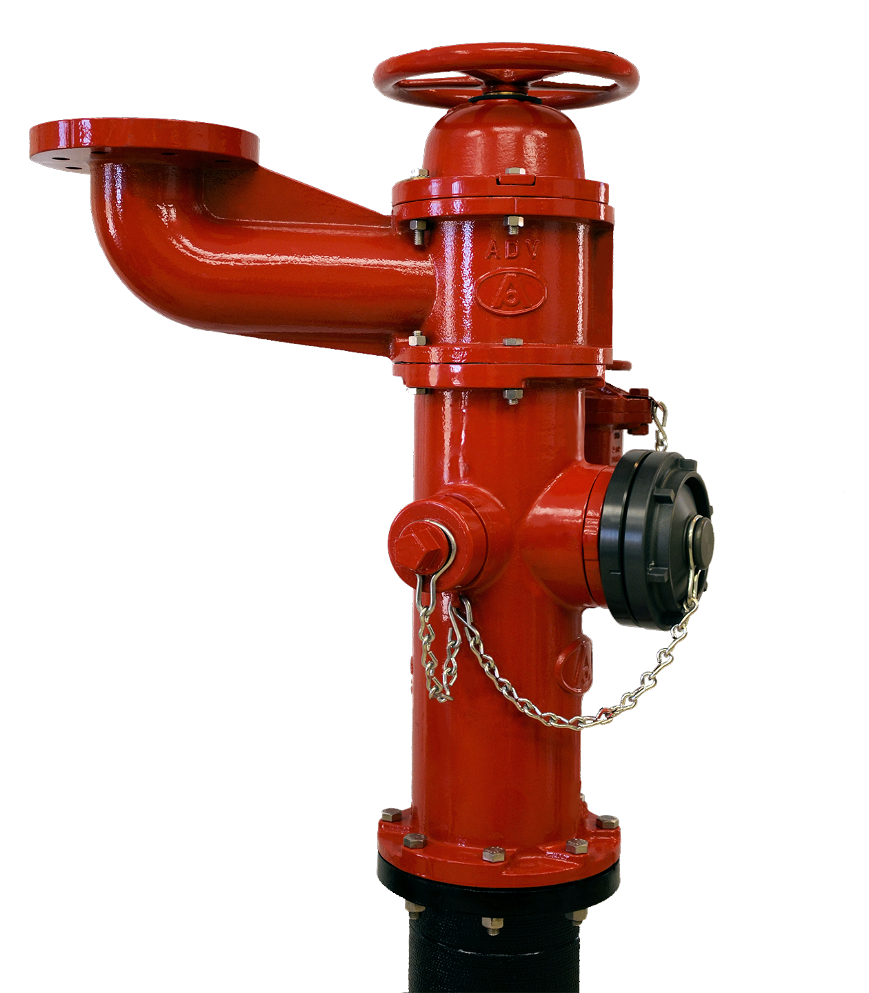
Fire Hydrant Valve Assembly
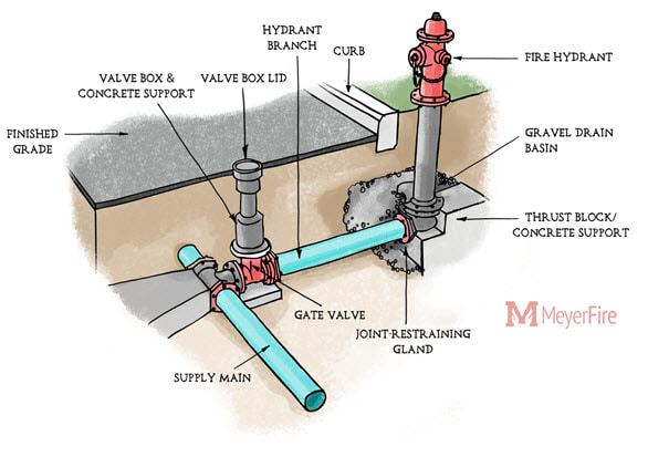
Breaking Down Components Of A Fire Hydrant

Fire Hydrant System Diagram Fire Hydrant System Fire Systems Fire Sprinkler System

Fire Hydrant Colors Their Nfpa Spectrum And Meaning

Metropolitan M 94 U S Pipe Valve Hydrant Llc
Brooks Emergency Response Products Hose Valves Hydrant Valves

Fire Hydrant 1650x2550 Drawing With Labels And Functional Descriptions Thingscutinhalfporn
Fire hydrant assemblies shall be designed to meet the requirements of this subsection and all other requirements listed in this section.
Fire hydrant valve assembly. Assemblies to your specification. Anubar test valve assembly. Single point booster valves. A fire hydrant system block plan is an indelible diagram mounted within the booster cabinet pump room and fire control room that illustrates the primary features of the fire hydrant system including the water supply location dimensions location capacity of each water storage or tank location quantity of each valve location of each pump pressure flow rating of the pumps location.
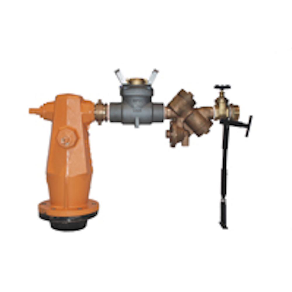
This may be as simple as an attack hydrant requirement such as a dual hydrant riser or a more complicated fire brigade quad booster point complete with feed hydrants isolating and check valves. Assemblies booster hydrant booster and hydrant assemblies consist of arrangements of valves pipe work to suit specific site fire protection needs. Stainless steel flexible pump connectors. Fire hydarant landing valves.
There are 3 main types of hydrant assemblies a perpendicular assembly a parallel assembly and an assembly over the main. Fire hydrant suction booster assemblies. Waste test valve. Fire hydrant assemblies shall be designed to withstand the working pressures shown on the plans or a design working pressure of 150 psi whichever is greater.
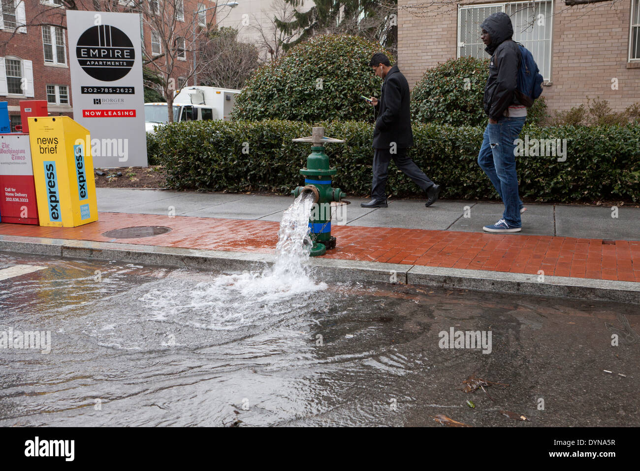
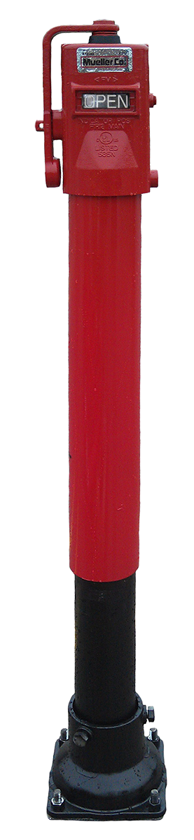
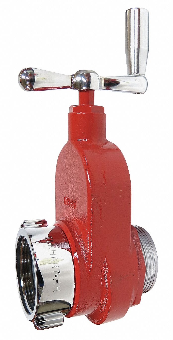
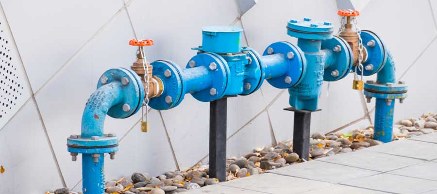
Fire hydrants are typically coupled with a watch or gate valve which shuts off the water source from the main line allowing maintenance repair or replacement of the hydrant.
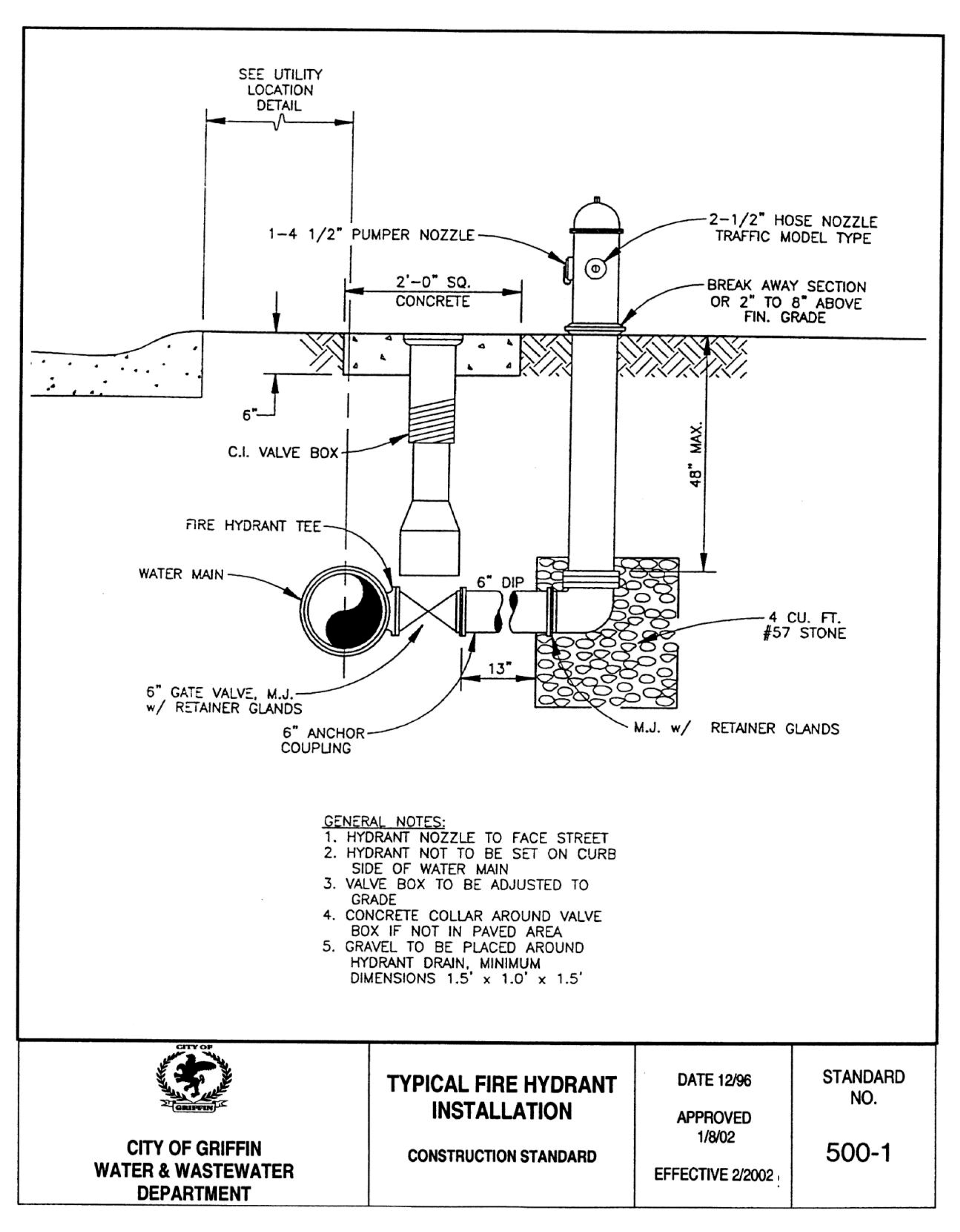
Article 15 Fire Safety Systems Code Of Ordinances Griffin Ga Municode Library
Http Mh Valve Com Upl Downloads Resources Product Brochures Model 129 Fire Hydrant Pdf
Https Www Jstor Org Stable 41252933

Animation Of Avk Dry Barrel Fire Hydrant Youtube
Https Www Hixsonutility Com Assets Pdfs Hixson Utility Construction Standards 2019 Pdf
Firewize Fire Hydrant Systems
Pollardwater 60 Psi Assembled Fire Hydrant With Bleeder Valve P67020lf Ferguson

5 1 4 American Darling B 84 B 5 American

Fire Hydrant Backflow Preventer With Relief Valve

Corrosion Damage Failed Fire Hydrant Imca
Mueller International Division Mueller Company Water Products

Fire Hydrants Mueller Co Water Products Division
Zurn 2 In Hydrant Backflow Meter 2 975xlhbm The Home Depot
Seasonal Concerns

5 1 4 American Darling B 62 B 5 American

Watermaster Fire Hydrants
Https Engineering Provwater Com Eng Forms Constserv Hydrantinstallationdetails

Ul Fm Wet Barrel Fire Hydrant United Water Products
Https Encrypted Tbn0 Gstatic Com Images Q Tbn 3aand9gctxf Zf1qc Lu Tfge4zz7zu Blah7cvxgydnhjztc7aa Thv0v Usqp Cau

Fire Hydrant Landing Valve Dixon Valve China
Fire Hose And Hydrant Valves Grainger Industrial Supply

Ul Fm Npt Female Outlet Angle Hose Valves Mafco Fire Fighting Equipment Fire Hydrant Valves Fire Hose Nozzles Fire Hose Coupling Manufacture
Https Www Muellercompany Com Sites Muellercompany Com Files Uploads Media Mueller Fire Protection Products Brochure English Form 12999 Pdf

Fire Hydrants Mueller Co Water Products Division
American Darling B 84 Bb 5 Industrial Fire Hydrant American
Https Www Joneswaterproducts Com Sites Joneswaterproducts Com Files Uploads Media 12492 Jones Brochure Wet 20barrel 20fire 20hydrants Web 0 Pdf
American Flow Control Waterous Pacer 4 Ft Mechanical Joint Assembled Fire Hydrant Wb 67 250 Ferguson

Hydrant Valve Ss Hydrant Valve Wholesale Trader From Ghaziabad

Hydrant Valve Nozzle Fire Hose Type 1 Minh Sang

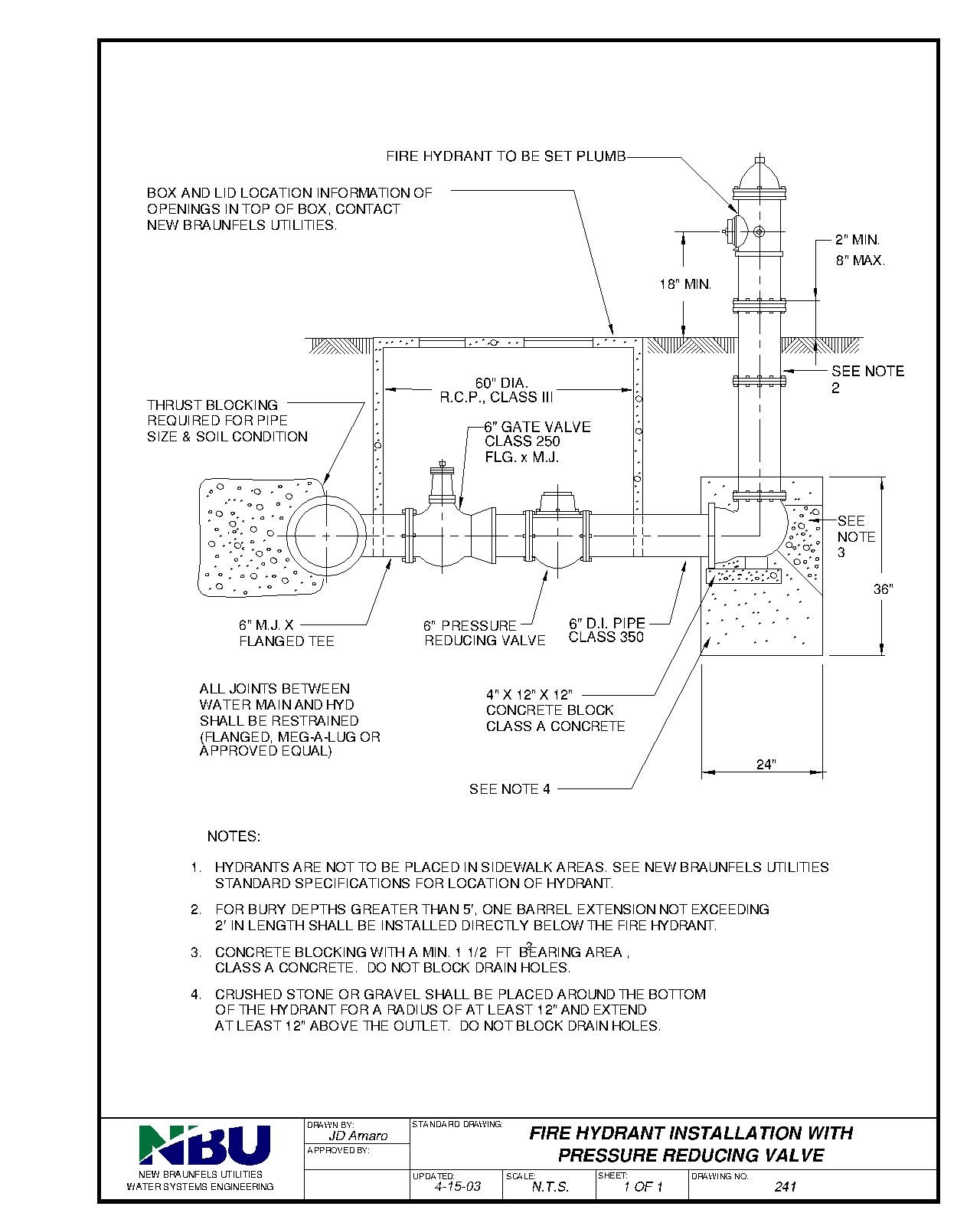
Standard Details

Guide To Fire Hose Reels And Racks For Standpipe And Hose Systems

Fire Hydrant Diffuser Piezo Pitot Tube Assembly With Snubber 1 4 Bleeder Valve Ebay
How Do Fire Hydrants Work Youtube
Water Connection Policy New Braunfels Utilities
Getting It Right The First Time Water Meter Installation Guide
Double Check Detector Assembly Backflow Assemblies The City Of Portland Oregon

1966 Yellow Fire Hydrant Iowa Valve Co Oskaloosa Model 50 Restored Hydrant Fire Hydrant Fire

Fire Dixon Valve Australia

Angle Valves In Fire Protection Plumbing And Water Based Systems
Https Www Mahaskacounty Org Wp Content Uploads 2009 05 Pricebook 3609 Working Pdf

2 Deringer 30g Double Check Detector Assembly Backflow Prevention Valve With Os Y Gate Valves Dcda Ii

Pre Assembled Riser Kits